


Description
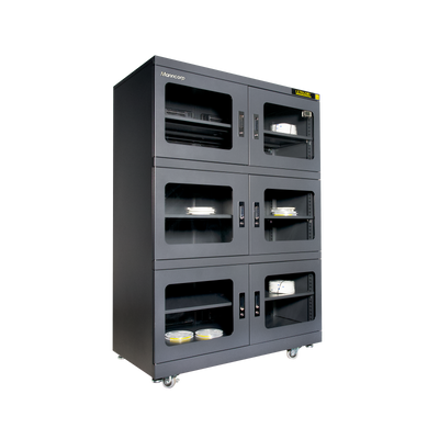
Protect_msd
Restore_and_store
Specifications
Features
Feeders
Machine_configurations
Applications
Profile_predictions
Performance_charts
Video
Navigator_software
Process_window
Add_ons
Temperature_tolerance
Includes
Add_fluxing
Machine_options
Software_options

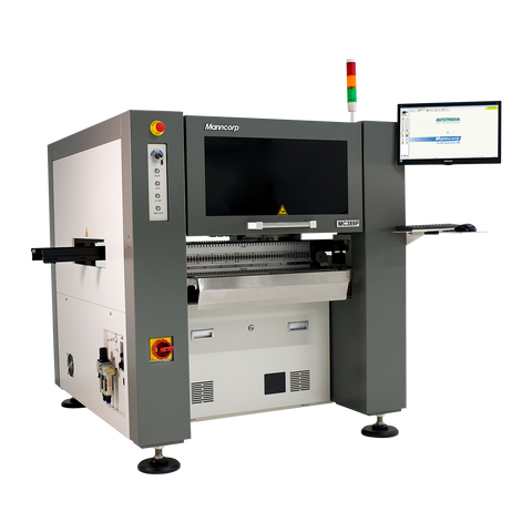
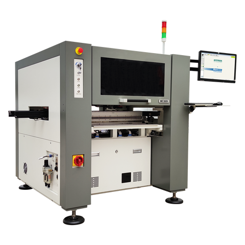
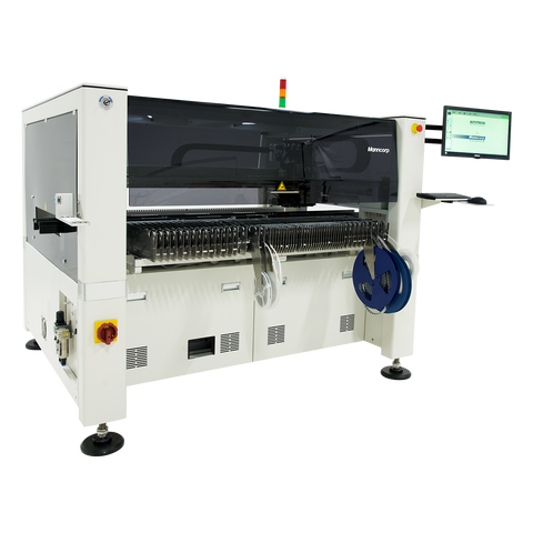
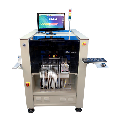
Huge Feeder Capacity & Placement Area
The MC388 offers unmatched feeder capacity and board handling flexibility, making it ideal for high-mix, high-volume production. In its batch or standalone configuration, it can be equipped with two additional 32-port feeder racks, increasing its total feeder capacity to an impressive 256. This extensive capacity allows for virtually zero job changeover time, maximizing uptime and throughput. Even when fully loaded with feeders, the MC388 maintains a spacious placement area of up to 1200 x 408 mm (47.2" x 16"), accommodating large panels and complex assemblies with ease.
When configured as an inline machine with the largest available board holder, the MC388 supports up to 192 feeders mounted on the front and rear. Despite the reduced footprint, it still provides a generous placement area of 1200 x 370 mm (47.2" X 14.6"), which can be flexibly shared between PCB panels, waffle trays, and cut strip tape holders. Whether you're running a dedicated line or a dynamic job shop, the MC388 offers the capacity and adaptability to meet your production demands.

Quickly and Accurately Place Just About Any SMD Component
The MC388 is built for precision across the full spectrum of SMD components, from the tiniest 01005 chips to large components measuring up to 100 x 150 mm. With a standard optics package and advanced motion control, it achieves placement accuracy of 30 µm at 3 Sigma, making it ideal for both dense, fine-pitch assemblies and large-format boards.
Its advanced alignment system uses a dual-vision approach: Cognex® on-the-fly cameras mounted on the placement heads work in tandem with a stationary upward-looking camera. This full-vision alignment technology precisely matches component leads, balls, or bumps directly to PCB pads, eliminating placement errors often seen in systems that align only to the component body. The result is highly accurate, repeatable placement-even for complex and irregularly shaped parts.

Consistency and Long-Term Dependability
Consistent results are non-negotiable, regardless of whether you're producing in-house or assembling boards for customers. The MC388 delivers with a rugged mechanical design and precision-engineered components that work together to maintain high accuracy and repeatability-even at full production speed.
At its core is a rigid, welded steel frame supporting a precision ball-screw system, advanced servo motors, and non-contact rotary encoders-all optimized for smooth, stable motion and reliable placement performance.
Your investment is protected with a standard 1-year warranty, plus built-in remote diagnostics for fast, expert support when you need it. With the MC388, you get more than just a machine, you get a performance-driven platform backed by responsive service and lasting peace of mind.

Set Up to Suit Your Needs
The standard MC388 comes equipped with a 3-stage, single-lane conveyor system featuring a SMEMA interface and automatic width control for PCBs up to 650 mm wide. For manufacturers working with longer boards-such as LED lighting panels-two extended handling options are available.
The first is a single-stage 1.2-meter conveyor upgrade that enables the MC388 to process boards up to four feet long in a single pass. Alternatively, a dual-stage conveyor option increases the maximum PCB length capacity to 1.5 meters, offering even greater flexibility for oversized or panelized assemblies.
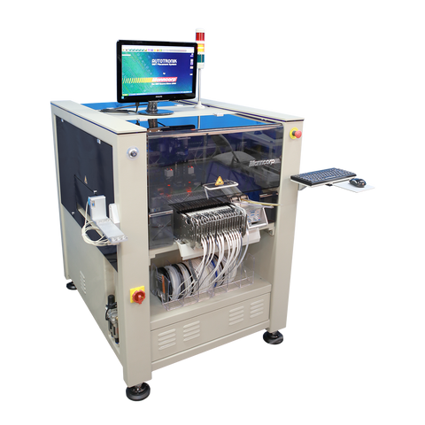
For applications that prioritize feeder capacity and quick changeovers, the MC388 is also available in a batch or standalone configuration, which unlocks its full 256-port feeder potential for high-mix, multi-job production environments.

User-Friendly, Field-Tested Software Built for Efficiency
The MC388 runs on the same powerful, Windows®-based software platform used across the entire MC Series, refined over more than a decade through real-world customer feedback. The result is a system that is not only reliable and stable but also remarkably easy to use, even in demanding production environments.
Programming can be completed through CAD file import and conversion, manual teaching, or direct entry. After CAD import, users simply follow intuitive setup steps to configure the PCB layout, assign feeders, and define component placements making job setup fast and straightforward. Component data integrates seamlessly with the Smart Feeder system, streamlining both inventory control and production preparation. A built-in virtual PCB simulator visually displays the programmed assembly, allowing for quick verification of accuracy before production begins.
The production screen offers real-time monitoring of all pick camera images and provides clear visibility into production speed, current run time, task lists, and PCB status. The system tracks component placement in real time, enabling production to resume exactly where it left off in the event of an interruption. Operators can make on-the-fly adjustments to feeder settings, part placement, speed, or component data without ever leaving the production window, ensuring continuous workflow and maximum uptime.
| Placement Specifications | |
|---|---|
| Number of Placement Heads | 4 |
| Placement Rate (IPC-9850)* | 8,000 CPH |
| Placement Rate (Max.) | 10,500 CPH |
| Placement Accuracy | 30 µm, 3 Sigma |
| Minimum Component Size | 01005 |
| Maximum Component Size | 100 mm x 150 mm (3.94" x 5.9") |
| Minimum Component Lead Pitch | 0.3 mm (0.012") |
| BGA/CSP Placement Capability | Yes - Standard |
| Alignment Method | Dual-Vision Alignment System |
| Pick Up Specifications | |
| Nozzle Changer | Included |
| Number of Nozzles | 22 |
| Accepts Additional Nozzles | Yes |
| Integral Vacuum | Yes |
| PCB Specifications | |
| PCB Loading Method | 3-Stage Inline Single-Lane Conveyor standard. Dual lane, single stage and dual stage available as well as no conveyor (batch / standalone operation) |
| Maximum Placement Area | 350 mm x 1250 mm (13.7" x 49.2") w/ conveyor 410 mm x 1100 mm (43.3" x 16") w/o conveyor |
| Fiducial Recognition/ Coordinate | Yes |
| Bad Mark Detection | Yes |
| Feeder Capacity | |
| Maximum Number of Feeder Ports | 192 w/inline conveyor 256 w/batch configuration |
| Programming | |
| Operating System | Windows Based |
| PC, Keyboard, Mouse | Yes |
| Monitor | Flat LCD |
| Teaching Camera | Yes |
| Numeric Data Entry | Yes |
| CAD Download | Yes |
| Step and Repeat for Matrix Boards | Yes |
| Bar Code Reader for Feeders & Packaging | Yes |
| MIS and Optimization Functions | Yes |
| Off-Line Programming | Yes |
| Dispenser Specifications | |
| Dispensing Head | Optional |
| Dispense Method | Time/Pressure |
| Dot Size/Placement Speed | Down to 0.5 mm |
| Mechanical Specifications | |
| X-Y Axis Drive Mechanism | Ball Screw |
| X-Y Axis Drive Motors | AC Servo |
| X-Y Axis Encoding | Rotary |
| X-Y Axis Resolution | 0.005 mm (0.0002") |
| Z Axis Drive Motor | DC Servo |
| Z Axis Encoding | Rotary |
| Z Axis Resolution | 0.02 mm (0.0008") |
| θ Axis Drive Motor | DC Servo |
| θ Axis Encoding | Rotary |
| θ Axis Resolution | 0.045° |
| θ Axis Range of Motion | 360° |
| Physical Specifications | |
| Overall Dimensions (Approx. L x W x H) | 2040 mm L x 1530 mm W x 1486 mm H (80" x 60" x 58") |
| Approx. Net Weight | 1950 Kg (4300 lbs.) |
| Facility Requirements | |
| Standard Voltage | 200-230 VAC, 50/60 Hz, 7A |
| Air Pressure | 80 psi, 16 CFM |
| Service and Support | |
| Remote Diagnostics | Ethernet |
| Warranty (Major Components) | 1 Year |

Smart Feeder Integration for Reliable Assembly
Every MC Series pick and place machine includes fully integrated smart feeder management and control software—built into the system from the ground up to enhance reliability, streamline efficiency, and ensure traceability throughout production. Each smart tape feeder features a DB-9 interface connector that plugs into any MC Series smart feeder base, enabling direct communication between the feeder and the machine’s software. A built-in memory module stores a unique feeder ID and essential component data, such as assigned port, feeder size and type, component value, lot and date codes, starting quantity, index increments, and package type.
To simplify job setup even further, an optional barcode reader can scan the part code on a reel and automatically upload all relevant information into the feeder. This eliminates manual data entry, reduces setup time, and prevents errors. Once connected, the system instantly applies the correct parameters, ensuring the right parts are always placed in the right positions. This seamless hardware-software integration allows MC Series machines to maintain consistently high assembly accuracy and efficiency, run after run.

New Innovative Feeder with Built-In OLED Display – KFTA3D Series
This next-generation smart feeder features an integrated OLED display and internal memory that continuously stores and updates key component information. Operators can instantly view reel quantities, feeder slot locations, part numbers, and part values whether the machine is running or offline. With real-time data visible directly on the feeder, setup becomes faster, more accurate, and less error prone. This added layer of visibility ensures the right components are loaded correctly from the start, preventing costly mistakes before they reach the inspection stage.
An internal battery ensures that stored data remains accessible even when the feeder is disconnected from the machine. Whether you’re tracking part usage during production or verifying setup offline, the system provides a consistent and reliable overview of component consumption. Additionally, these feeders are designed for efficient use of rack space; a 12 mm feeder only occupies a single slot, allowing for higher feeder density and greater flexibility during job setups. By shifting critical data access to the point of use, these smart feeders significantly improve both traceability and productivity in any high-mix SMT environment.

Universal Smart Stick Feeders for Maximum Flexibility
Manncorp’s smart stick feeders offer seamless integration with MC Series pick and place machines and can be positioned directly alongside smart tape feeders for efficient use of feeder rack space. Available in 5, 10, or 20-lane configurations, these feeders provide the flexibility needed for a wide range of component types and production requirements.
Using DB-9 interface connectors, each feeder communicates directly with the system software through the smart feeder base. Built-in memory modules store unique ID numbers that link each lane to its specific feeder position and associated data, including component specifications, belt indexing increments, and precise on/off timing for the vibratory mechanism. This intelligent design ensures accurate, consistent part delivery while simplifying setup and minimizing the risk of operator error.

Flexible Tray and Cut Tape Handling for MC Series Machines
MC Series pick and place machines feature spacious, open work areas designed to accommodate a variety of component presentation methods, including waffle trays and cut tape strips, for maximum flexibility during production.
The TS-1 Waffle Tray Holder occupies approximately 13” x 5.5” (330 mm x 140 mm) of the work area and is designed to securely hold a standard 12.4” x 5.35” (316 mm x 136 mm) JEDEC matrix tray—or up to two cut strip tape holders. Its adjustable design supports a wide range of smaller matrix tray and waffle pack combinations and can easily be modified for custom tray configurations as needed.
For low-quality components or those supplied in short tape lengths, CST Cut Strip Tape holders offer a practical solution. These holders allow operators to present components that are not long enough to be used with standard tape feeders, helping reduce waste and improve efficiency. Standard holders are available for 8 mm, 12 mm, 16 mm, and 24 mm tape widths, with additional sizes available upon request.
Smart Feeder Software: Seamless Setup, Tracking, and Changeover
Included as standard on all MC Series pick and place machines, Manncorp’s advanced smart feeder software simplifies and accelerates production with intelligent features that reduce setup time and eliminate manual data entry. From automatic quantity tracking to feeder position verification, the system ensures accurate, repeatable results across both short runs and high-volume jobs.
One of the key capabilities is automatic component quantity tracking. During production, the software continuously monitors component usage and updates each feeder’s onboard memory with the quantity remaining on the reel. This data is retained even after the feeder is removed. When reloaded—even for a different job—the feeder automatically communicates its remaining part count to the assembly program, allowing production to resume without recalibration or manual input.
Feeder position verification ensures components are being pulled from the correct locations. When optimized feeder positions are used, the machine compares smart feeder IDs with predefined slot data to confirm correct placement. If optimized positions are not used, the system can perform position scanning, identifying each feeder’s location automatically and mapping it to the corresponding pick-up point in the assembly file for fast, error-free changeovers.
To support flexible production environments, quick-change feeder location functionality allows operators to move feeders to new slots or maintain the same layout across consecutive runs without editing the pick and place program manually. For even greater convenience, an optional barcode reader can capture component data such as part value, lot code, date code, and starting quantity directly from packaging—cutting out time-consuming manual entry and reducing the risk of data entry errors.

Smart Tape Feeder Carts for Secure Storage and Off-Line Kitting
Safely transport, store, and organize your Smart Tape Feeders with Manncorp’s durable, dual-tiered Smart Tape Feeder Storage Cart. The FR-ST64 model (pictured) holds up to 64 individual 8 mm Smart Tape Feeders, making it ideal for off-line kitting and streamlined production preparation. Designed for mobility, the cart moves easily from the kitting area to the production line, helping operators stage feeders in advance for faster setup and changeover.
Built with heavy-duty tubular steel construction, the cart holds each feeder securely in place while protecting against bumps and impact during transport. Whether you’re preparing for a high-mix production run or simply looking to keep your feeders organized and damage-free, the FR-ST64 is a reliable, space-saving solution for any SMT operation.

Automatic Index Adjustment to Eliminate Pickup Errors
MC Series pick and place machines feature automatic index adjustment using vision-board alignment. When a new reel is loaded into a feeder, the machine can detect slight offsets in tape pocket position and automatically advance or reverse the feeder to correct it—ensuring accurate component pickup from the start. This is especially valuable when switching reels, as minor misalignments between tapes can lead to placement errors. For reels with looser tolerances, the system can be set to verify alignment and adjust indexing on every pickup, preventing recurring errors and maintaining consistent, reliable performance.
Inline Configuration (Standard)

| Max. Placement Area | 350 mm x 1250 mm (13.8" x 49.2") |
| Maximum Number of Feeder Ports | 192 |
| Max. Feeder Ports (Front) | 96 |
| Max. Feeder Ports (Rear) | 96 |
| Max. Feeder Ports (Right) | 0 |
| Max. Feeder Ports (Left) | 0 |
Batch/Standalone Configuration (Option)

| Max. Placement Area | 410mm x 1100mm (16" x 43.3") |
| Maximum Number of Feeder Ports | 256 |
| Max. Feeder Ports (Front) | 96 |
| Max. Feeder Ports (Rear) | 96 |
| Max. Feeder Ports (Right) | 32 |
| Max. Feeder Ports (Left) | 32 |