


Description
Protect_msd
Restore_and_store
Specifications
Features
Jet_dispenser
Feeders
Machine_configurations
Applications
Profile_predictions
Performance_charts
Video
Navigator_software
Process_window
Add_ons
Temperature_tolerance
Includes
Add_fluxing
Machine_options
Software_options

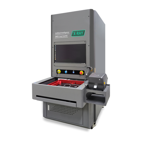
High-Resolution Imaging with Microfocus Technology
The X6800 delivers exceptional detail for inspecting small defects in dense SMT assemblies.
- Microfocus X-ray: 40–90kV with 5 µm focal spot
- High clarity: detects voids, microcracks, and trace breaks
- HD detector: sharp, high-contrast imaging

Advanced Tilt and Viewing Flexibility
Flexible viewing angles make it easier to inspect hidden defects.
- Up to 60° tilt: clear oblique-angle inspection
- Hidden defect detection: ideal for BGAs and QFNs
- Large work area: 530 × 530 mm, 10 kg capacity

Smart Automation and Precision Analysis
Advanced software and automation tools streamline inspection and improve consistency.
- Auto navigation: faster setup and positioning
- Advanced analysis: BGA voids, solder coverage, measurements
- Programmable workflows: repeatable, high-volume inspection
- 5-axis control: precise sample manipulation
Built for reliability and ease of use, the X6800 supports efficient, high-precision inspection in demanding environments.
| X-Ray Source | |
|---|---|
| Type | Closed, microfocus |
| Max. Tube Voltage | 90kV |
| Max. Tube Current | 200 µA |
| Focal Spot Size | 5 µm |
| Function | Auto Preheat |
| Flat Panel Detector | |
| Effective Area | 130 mm x 130 mm |
| Pixel Size | 85 µm |
| Resolution | 1536 x 1536 |
| Frame Rate | 20 fps |
| Tiltable Angle | 60° |
| Table | |
| Size | 530 mm x 530 mm |
| Detectable Area | 500 mm x 500 mm |
| Max Load | 10 kg |
| Equipment | |
| Magnification | Geometry 200X System 1500X |
| Inspection Speed | Max 3.0s/point |
| Dimensions | 53.5" L x 53.7" W x 68" H 1360 (L) x 1365 (W) x 1730 mm (H) |
| Weight | 1200 kg |
| Power Supply | AC220V 50/60Hz |
| Max Power | 1500W |
| Industrial PC | I5 CPU, 8GB RAM, 500GB SSD |
| Displayer | 24" HDMI LCD |
| Safety | |
| Radiation Leakage | No leakage, international standard: ≤1μSv/h |
| Lead Glass Observation Window | Transparent lead glass window shields radiation to observe the inner status |
| Window and Back Door Safety Interlock | Once users open the window or back door, the x-ray tube will power off immediately. When the window or back door is open, users cannot turn on the x-ray. |
| Electromagnetic Safety Switch | Lock once the x-ray is on, users can't open the observation window. |
| Emergency Stop | Next to the operation position, press to power off |
| Tube Protection | Users can't leave the software if you don't close the x-ray tube. |
| Function Module | |
| Operation | Keyboard and mouse can finish all operations |
| X-Ray Tube Control | Using mouse to click the X button can turn on or off the x-ray. The real-time tube voltage and current value will display beside, users can click up and down button, or drag the slider, or type to adjust. |
| Status Bar | Indicates the interlock status, pre-heat status, and x-ray status by flashing alternately red and green. |
| Image Effect Adjustment | The brightness, contrast and gain of the image can be adjusted freely to achieve a satisfactory result. |
| Product List | Users can save the inspection parameters such as Z-axis position, brightness, contrast and gain, and can directly call the parameters when inspecting the same product, to improve the inspection efficiency. |
| Navigation Window | After the camera takes a photo of the table, click anywhere in the photo, the table will move to the place you click and display on the screen. |
| Motion Axis Status | Display real-time coordinates |
| Inspection Result | The measurement results (voids rate, distance, area, etc., set by users) display in order. |
| Speed Control | The movement speed of each axis can be adjusted to slow, normal and fast. |
| Voids Rate Measurement | |
| Automatic Calculation | Click two points to determine a rectangle. The software automatically finds and measures the edge of the solder ball in the rectangle, the pad and the internal voids, and can get the data of the voids rate, the area of the solder ball, the circumference, the biggest void's rate, the length and width, and indicates NG or OK by red and green. |
| Parameters Adjustment | Users can adjust the grayscale threshold, pixel, contract, size filtering and other parameters to get accurate results of automatic calculation. |
| Add Voids Manually | Users can draw a polygon or a free figure and calculate it as a void into the void rate. |
| Save Parameters | Users can save parameters such as grayscale threshold, pixel, contrast, size filtering and other parameters, and can directly call the parameters when detecting the same product to improve the detection efficiency. |
| Other Measurement Functions | |
| Distance | Measure the vertical distance to the baseline |
| Distance Rate | Measure the soldering rate of the through-hole |
| Angle | Measure the angle between the baseline rays |
| Radius | Measure round components, such as solder balls |
| Perimeter | Measure square components |
| Automatic Inspection | |
| Manual Setting | Users can set any positions on the table as inspection points; the software will automatically inspect and save the image. |
| Array | For the regular inspection points, users only need to set two of the inspection points and the number of rows and columns; the software will automatically inspect each point and save images. |
| Automatic Identification | For inspection points with obvious features, the software automatically identifies the positions, takes measurements, and saves the image. |
More from X-Ray Inspection Systems