


Description
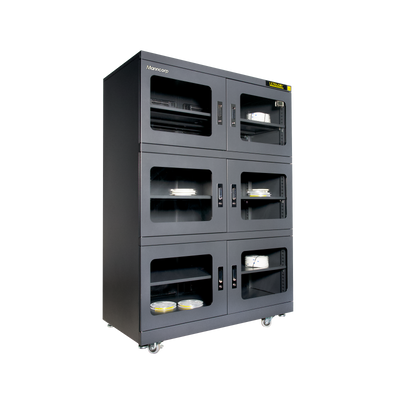
Protect_msd
Restore_and_store
Specifications
Features
Feeders
Machine_configurations
Applications
Profile_predictions
Performance_charts
Video
Navigator_software
Process_window
Add_ons
Temperature_tolerance
Includes
Add_fluxing
Machine_options
Software_options

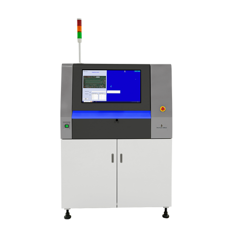
Smart, Compact Inline AOI with Intelligent Board Handling and Offline Programming
The Sherlock 300I seamlessly integrates into your existing SMT or through-hole production line, providing comprehensive inspection either before or after reflow, or following wave soldering. Its compact footprint and advanced, algorithm-driven software ensure thorough defect detection—including solder joint quality, component presence, polarity, and placement—without slowing down your line. To maximize productivity, programming can be performed offline at a separate station, eliminating downtime during recipe creation or updates.
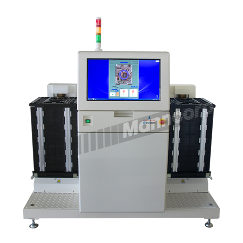
After inspection, the Sherlock System communicates directly with downstream equipment to route boards appropriately. Accepted PCBs proceed automatically down the line or into a good board rack, while rejected boards are flagged for rework. Manncorp also offers an optional AOI rejection conveyor, which stops failed boards for operator review or diverts them to a dedicated rework rack—enhancing traceability and quality control without interrupting the production flow.

High-Speed, Low-Vibration Inspection Designed for Pre-Reflow PCBs
All Sherlock Systems feature a high-rigidity X-Y biaxial drive mechanism that enables smooth, high-speed movement of the imaging unit while maintaining exceptional accuracy and stability. Its low-vibration camera drive is specifically engineered for inspecting PCBs before the reflow process—when components are not yet soldered in place and especially sensitive to movement. During inspection, the PCB remains stationary on the conveyor, allowing for clear image capture without disturbing parts that have not been fixed.
To further reduce vibration and enhance inspection reliability, the system incorporates advanced motion control technology originally developed for high-speed semiconductor wafer handling. This technology precisely manages acceleration and deceleration, minimizing mechanical stress and ensuring stable imaging conditions even during rapid inspection cycles. The result is a reliable, non-intrusive AOI solution for delicate, pre-reflow assemblies.

Enhanced Dual-Lighting for Accurate Solder and Component Evaluation
The Sherlock System incorporates a sophisticated RGB lighting setup designed to improve both the clarity and speed of solder joint inspections. This lighting method distinguishes flat solder pads in red while highlighting sloped fillet regions in green or blue, delivering a single image that clearly separates horizontal from angled surfaces. When solder joints are properly formed, they display three distinct color zones—making it straightforward to evaluate coverage, shape, and overall integrity. When paired with high-speed imaging, this technique ensures fast and accurate inspections ideal for high-throughput production lines.
Beyond RGB illumination, Sherlock Systems also include high-intensity white LEDs that ensure precise analysis of component features such as color codes, text markings, orientation, and alignment. This facilitates reliable identification of resistor bands, connector labels, OCR text, and polarity indicators. The uniform lighting and shadow suppression contribute to low false-call rates and consistent inspection accuracy across a diverse range of components.

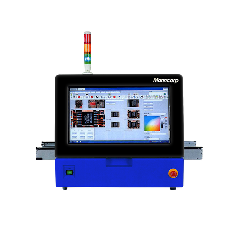
Simplified Programming, Powerful Performance
The Sherlock System makes AOI programming and operation easier than ever with its user-friendly, touch-screen interface. Built-in automation features—such as automatic pick-and-place data conversion and CAD import—streamline setup, while a robust, customizable parts library eliminates the need for highly skilled AOI operators. These tools dramatically reduce programming time and simplify inspection setup for even complex boards.
Unlike the limited libraries found in many AOI systems, the Sherlock parts database contains extensive inspection parameters for each component. These include optimized image processing settings, specific lighting conditions, defined inspection zones, and more. Users can quickly modify existing parts or create custom ones, ensuring the system adapts easily to unique production requirements.
Designed with usability in mind, the software provides an intuitive experience for both novice and experienced operators. A helpful “Navigation Mode” guides users step-by-step through programming and inspection processes, and built-in online help is available at any time for immediate support. The full user manual is integrated into the software, with an easy-to-use function lookup tool. All advanced functions and their attributes are clearly explained, enabling users to fully leverage the system's capabilities without extensive training.

More Than Inspection — Improve Process Performance
Take your inspection capabilities further with the addition of Statistical Process Control (SPC) software. Running independently from the Sherlock System on a separate PC, SPC helps uncover early signs of process variation, monitor long-term performance, and identify recurring quality issues. By converting inspection data into clear, actionable information, this tool empowers smarter decision-making that leads to higher yields, fewer defects, and better overall process control.
To streamline operations and boost traceability, the Sherlock System’s built-in camera can read both linear and 2D barcodes—removing the need for dedicated scanning hardware. It also includes OCR functionality, enabling accurate reading of part numbers, component labels, and other printed data as part of the automated inspection workflow.

Trace and Repair Made Easy
Sherlock's dedicated optional repair station software streamlines the rework process by giving operators detailed visual and textual information for each rejected PCB. At the repair station, personnel can instantly access high-resolution images of the failed component, along with its part name, location on the board, and reason for rejection. When paired with a barcode scanner, the system allows users to instantly call up board-specific data with a quick scan of the PCB’s label—saving time and reducing the risk of handling errors.
Inspection and repair history is fully searchable by serial number, making it easy to track issues and confirm completed fixes. When connected with Sherlock's SPC (Statistical Process Control) software, the system also compiles and analyzes repair data to identify trends and problem areas—providing end-to-end traceability and enabling continuous improvement across your production process.
| Sherlock 300I Specifications | |
|---|---|
| Minimum Component Coverage | 01005 (12.4 µm/pixel) 0201 (18.7 µm/pixel) Standard Lens |
| Minimum PCB Size | 2" x 2" (50 mm x 50 mm) |
| Maximum PCB Size | 13" x 9.85" (330 mm x 250 mm) |
| Thickness | .5-2mm |
| Maximum Weight of PCB | 1 kg |
| Topside Clearance | 25 mm (12.4 µm/pixel) 30 mm (18.7 µm/pixel) |
| Bottomside Clearance | 70 mm |
| Conveyor Height | 920 +/- 50 mm |
| Camera Resolution | 12.4 µm/pixel 18.7 µm/pixel |
| Inspection Speed | 5,000mm²/s |
| Imaging Range / Field of View | 25.4 x 13.5 mm (12.4 µm/pixel) 38.3 x 20.3 mm (18.7 µm/pixel) |
| Depth of Field | 6 mm (12.4 µm/pixel) 10 mm (18.7 µm/pixel) |
| Repeat Position Accuracy | +/- 50 µm |
| Camera | 2 megapixel |
| Lighting | RGB and warm-white illumination in 3-ring arrays |
| Flow of PCB | Right to left/Left to Right |
| Machine Interface | SMEMA |
| Drive system of imaging unit | High rigidity biaxial belt drive |
| PCB Clamp | Air Clamp |
| Conveyor Width Adjustment | Automatic |
| Offline Programming | Optional |
| Repair Station Software | Optional |
| SPC Software | Optional |
| Monitor | 21.5" touch panel display |
| Computer Control | Windows 10 Pro 64 bit, 8G memory |
| Power Requirements | 100-240 VAC +/- 10% single phase, 50/60 Hz |
| Compressed Air | 72 psi, 5 l/min |
| Dimensions (L x W x H) | 24" x 30" x 51" (620 x 758 x 1294 mm) (Alert light adds 11" (280 mm) in height) |
| Weight | 439 lbs (199 kg) |
| Warranty | 1 Year |
| Remote Service & Support | Included |
| 2-Day Remote Training | Included |
More from AOI Machines